
")
BSC 1


The BSC1 chamber design is similar to the original “Oslo chamber” (Langmoen & Andersen 1981) with later modifications (Dhanjal & Sears 1980, Alger et al 1984) to allow both interface and submerged methods of slice maintenance (Williams et al, 1993, Murphy et al, 1997, Bliss at al 2003). The temperature is controlled by a proportional control heating unit, the PTC03.
Features
- "Submerged” and “interface” methods of slice maintenance with same chamber
- Slices supported on removable insert, adaptable to your requirements
- Proportional temperature controller (PTC03) with low noise operation
- Modular, leak-proof design for years of service
The chamber is constructed from clear acrylic having a diameter of 100mm, height is 75mm and the base plate is 130mm in diameter. The slices rest on a nylon net fixed on to a removable insert, located in the centre of the chamber. Pre-oxygenated medium enters the main body of the chamber through a fine bore tube which spirals in the heated distilled water in the lower part of the chamber and enters the upper part of the chamber via a bubble trap.
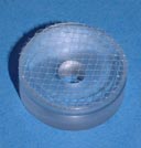
Inset
Depending on whether submerged or interface type preparations are required, the height of the perfusion fluid is adjusted at the exit well by means of a screw mechanism. In the case of interface preparations, the high oxygen tension is maintained by bubbling a 95% oxygen, 5% carbon dioxide gas mixture through a ceramic bubbler located in the lower heated part of the chamber. This moistened and warmed gas mixture enters the upper part of the chamber via "port holes" and is then deflected by a profiled lid across and downwards towards the centrally located slice preparation. The temperature in the upper chamber is maintained by ensuring that the medium and moistened gas mixture enter at the required temperature. This is dependent on the temperature of the lower chamber body which is warmed by a heating element controlled by the Proportional Temperature Controller PTC03.
Schematic diagram
The design of the chamber is modular to allow easy cleaning and replacement of parts. The heater and control sensor elements are screwed into the base of the chamber. The three main components: base, trough and upper chamber are screwed together. The trough which forms the heated water bath is over 10mm thick for durability, heat insulation and stability. Solution lines are HPLC type PTFE tubing which resists formation and adhesion of fungal growths.
Parts Description
[1] BUBBLE TRAP - helps to eliminate bubbles entering under the net insert
[2] HEAT EXCHANGER TO WARM INCOMING SOLUTION - solution enters area of slice at the set temperature
[3] TEMPERATURE CONTROL SENSOR - screwed into side for easy replacement
[4] HEATING ELEMENT - screwed into side for easy replacement
[5] OXYGEN/CARBON DIOXIDE GAS BUBBLER - long lasting ceramic air stone easy to clean and maintain
[6] EXIT FOR PERFUSION FLUID VIA SUCTION LINE - replaceable hypodermic needle sets fluid height