
")
Model 2100

Widely used Pulse Stimulator
Demo unit - Special offer: 20 % off - while stocks last
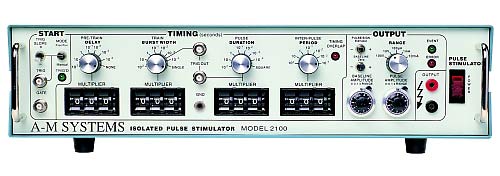
This optically Isolated Pulse Stimulator (A-M Systems Model 2100) has been designed for a wide variety of physiological stimulation requirements. A flexible, accurate system, it can be operated free running, manually triggered, or externally triggered. A TRIGGER indicator lights up when an acceptable trigger event is received. An EVENT indicator lights up whenever a pulse is delivered.
The operator describes the desired pulse train by setting four times; the delay time (time between trigger and the first pulse); train burst width time; individual pulse duration; and interpulse period (the duration of a single pulse on/off cycle). lf the period set is shorter than the pulse duration, a timing overlap error LED indicator warns the user of this condition.
For ease of use, the delay may be set to "none", so that no extra delay occurs between trigger and pulse output. The burst width may be set to "single", so that only a single pulse is output for a single triggering event. This has the additional effect of suppressing the post-pulse delay associated with the inter-pulse period, thus allowing the stimulator to become immediately retriggerable, instead of waiting until the end of the period. The pulse duration may be set to "square", automatically setting the period to exactly one half of the period.
The times are easily and rapidly set with leverwheel switches, which are much more convenient than thumbwheel switches. The timing accuracy is dependent only on a 10 MHz internal crystal clock which has an absolute accuracy of better than 0.02%, and timer-start jitter of ±250 ns (±2.5 µs in the 100 second range).
The full-scale amplitude accuracy is 1 %, with a voltage-mode output impedance of less than 100 Ω, and a current-mode output impedance of at least 1 MΩ . The output pulses may be monophasic (selectable polarity), or biphasic, in which a positive pulse is immediately followed by a negative pulse. The baseline amplitude is independently adjustable, up to ±10 % of the pulse amplitude range.
Features
- Wide timing range: 1 µs to 999.9 s
- Excellent timing accuracy: better than 0.02 %, with less than 250 ns jitter (less than 2.5 ps jitter on 100 s range)
- Optically-isolated, short-circuit protected output
- Calibrated current or voltage mode output: up to ±100 V, ±10 mA
- Mono- or bi-phasic pulse outputs
- Status indicators: operational state and setup/control errors Trigger outputs: for both individual pulses and the entire burst train
- Optical isolator-coupled output control
- No battery required! Isolation transformer powered output
Specifications
Physical Dimensions: 43.2 cm × 12.1 cm × 28.6 cm
AC Power. This is the standard power source. Either 110 V AC or 220 V AC may be used. This is set at the factory and must be indicated at the time the order is placed.
Each Isolated Pulse Stimulator is delivered complete with: Rack Mount Hardware; Instruction & Maintenance Manual
Accessories Available Separately:
# 7015 3' Cable-5-pin Connector to Dual-Banana Plug
# 7016 3' Cable BNC Connector to Dual-Banana Plug
# 7202 Extra Manual