
")
A-M Systems 2400

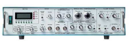
The Model 2400 is a low noise, full featured intracellular/extracellular amplifier designed for voltage clamping using patch electrodes on single channels or whole cells. Its unique design allows fast intracellular current clamp measurements with sharp electrodes. Advanced circuit design techniques using field programmable gate arrays eliminate noisy microprocessors.
Features
- Full-Function Patch Clamp Amplifier for both whole cells and patches
- True Current Clamp is 100 % stable with bandwidth of 200 kHz
- Switchable Dual Resistive Feedback Headstage
- Capacity, series resistance, and whole cell compensation
- 4-pole low pass Bessel filter
- Telegraph outputs for all major front panel controls
- Independent hold, offset, and tracking circuitry
- Displays command potentials, cell currents, and voltages
Specifications
Probe Gain and Bandwidth
|
Feedback Resistor |
Probe Gain |
Maximum Current |
Minimum Bandwidth |
|
10 MΩ |
10 mV/nA |
1000 nA |
100 kHz |
|
100 MΩ |
100 mV/nA |
100 nA |
100 kHz |
|
1 GΩ |
1 mV/pA |
10 nA |
60 kHz |
|
10 GΩ |
10 mV/pA |
1 nA |
40 kHz |
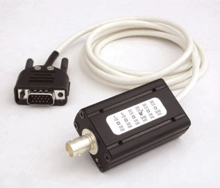
BNC input connector: 1 mm ground pin connector
The probe has three connections, the input BNC, a ground jack, and a guard jack.
The input BNC will hold any BNC style electrode holder, and is where any input signal should be connected. The center conductor is connected through a current limiting resistor to a field effect transistor amplifier. Other than the current limiting resistor there is no other protection to the probe so care must be taken to avoid electrostatic discharges. The outer conductor of the BNC is connected to a guard circuit. The guard is a buffered version of the input voltage, so care must be taken not to ground the outer conductor of the BNC.
Probe Case, Size: 54 mm long × 20 mm high × 36 mm wide
Maximum Instrument Noise
Voltage clamp modes measured with the internal 4 pole Bessel filter and minimum external noise
|
Bandwidth |
Headstage Resistor |
|||||||
|
10 MΩ |
50 MΩ |
100 MΩ |
500 MΩ |
1 GΩ |
5 GΩ |
10 GΩ |
50 GΩ |
|
|
1 kHz Theoretical Limit |
0.002 nA |
0.6 pA |
0.4 pA |
0.2 pA |
0.1 pA |
0.06 pA |
0.04 pA |
0.02 pA |
|
1 kHz |
0.003 nA |
0.7 pA |
0.5 pA |
0.5 pA |
0.5 pA |
0.5 pA |
0.5 pA |
0.5 pA |
Headstage
The probe is both a current to voltage converter and a voltage follower. The current to voltage converter used in voltage clamping has one of two high value resistors used for amplifying membrane currents. Below is a table of the different feedback resistor configurations of A-M Systems probes you can purchase from us.
Note: For proper operation, the purchase of a Model 2400 Patch Clamp Amplifier headstage and an electrode holder is required (order separately).
|
Catalog Number |
Resistor |
Maximum Current |
Probe High Gain |
Probe High Gain |
|
880210 |
10 MΩ |
1000 nA |
1 GΩ |
10 nA |
|
880218 |
10 MΩ |
1000 nA |
10 GΩ |
1 nA |
|
880222* |
100 MΩ |
100 nA |
10 GΩ |
1 nA |
* Standard headstage delivered with Model 2400 Patch Clamp Amplifier unless one of the other catalog numbers is selected.