
")
-
Home

-
Products
-
Amplifiers and other Electrophysiological Devices
-
Amplifiers
-
Modular Amplifier Systems
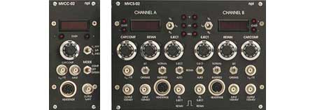
- Drug Application Modules
Results 1 - 3 of 3
Drug Application Modules


-
Home
-
Products
-
Amplifiers and other Electrophysiological Devices
-
Amplifiers
-
Modular Amplifier Systems
- Drug Application Modules